description of the project is finally perhaps the most 'controversial among fans of electronics: the' power supply for your lab bench. He was born
My idea discussed a little '(animated) with colleagues at the university', in relation to the device''ideal'' that would solve all the possible needs for food laboratory. At some point we created two lines of thought: those who said that power supply should be minimal, with only one adjustable output and''perfect'', and those who said that the panel had to find alternate space in all outputs, all the fixed voltages of 1.5, 3, 6, 9, 12, 15V, and at least two output variables, and of course strictly analog instruments.
was at that point I thought: Why 'does not achieve a modular structure, to dial as needed? In the end, a super-power-equipped as I can 'be exploited? Almost never!
I decided to divide the concept of''power'' into four basic sections: the section of raw power (transformer, bridge and capacitor), the regulator, the instruments and the Security section.
I decided it would be a good idea to make the individual units 'in separate boxes, to be connected as needed in order to make the structure flexible, besides' cleanest possible, since every time you are connected only with the combined 'you want.
confess that the idea came to me looking at the quantity 'industrial bushes and banana plugs that I bought last year at the Fiera di Pordenone, and which had remained unused for a long, long time .. It would be a shame not to use them, right?
was so 'that I began to realize the bank instruments, by enclosing it in a box model GEWISS 207.
These boxes are really ideal for prototype development and hobbies, plastic and 'great, it lets you work well and is' very strong, and also the bottom of the boxes and' full of ribs, good for fixing metal towers, transformers and everything 'else. In
''207''found space in a DC voltmeter and an ammeter fs 30V DC 3A fs, strictly analog, managed through a switching system that allows you to exclude the instruments (for more tests' at risk for their safety '!), to report the measures to a different mass, etc. .. The instrument and 'very versatile and I use it virtually forever.

The second unit, 'I realized that embraces the "brute power'', ie transformers, capacitors and bridges. Since these components much more' bulky, I used a box model GEWISS 209.

Initially I wanted to include only the components mentioned above, but then, given the abundance of space, I added a bit 'of''optional'', which now list:
-voltage network to 220 volts is sent through transformers to the relay ', operated by switches on the panel operating at 12 volts. I did not like the idea of \u200b\u200bhaving the 220 volt panel, And then I can always predict the activation of the relay 'on a remote, or automatic, although I have not yet implemented this function, relay and' master / slave only to the switches on the panel. A
-10W 12V transformer provides power for the vehicle mentioned above, and the LEDs that I'm going to put on the panel (still remains an intention, given the short time available).
-The main power transformer and 'was recovered from a plotter, and' has a primary dial 110-200-220-240V, and three secondary, and with 220 to provide primary, respectively, the AC voltages of 9, 18 and 27V.
-I initially thought of bringing only the winding 220 mostly primary, but then I thought of putting a 3-position switch, to choose whether to keep the processor off, whether to send the 220V winding winding''220''or''240'', so tensions have significantly more 'lower than nominal. This is me and 'useful for testing the behavior of the load for example in the case of low voltage, or to verify the autosuscettibilita' of a converter. In short, the difference between the voltages obtained at the secondary and not 'high, but it can' be helpful.
terminals of the three secondary windings of this transformer are brought directly to the front panel.
-I then mounted a second transformer, a toroidal 50W with 20V output 20 + central zero. The output in AC and 'brought to the front panel with three terminals, which should ever try a dual power supply.
-This second processor in addition to providing these tensions to the front panel, dual DC power internally at least a full, made a pair of regulators LM317-LM337. The output voltages range from 1.25 to about 25 volts for the positive branch, and from -1.25 to-25V for the negative branch, and are regulated separately by two excellent panel potentiometers. The maximum current of 1.25A for each branch and 'more' than enough food for the majority of projects that require single or dual power. Then taking the tension between the branch with positive and negative, can be get too high voltages up to 50V, a voltage outside the normal range of common bench power supplies, which almost always arrive up to 30 volts.
The regulators are attached to a heat sink on the right side of the''209''. On the left side
-mounted sink another two bridge rectifiers 50A, accompanied by a 10,000 uF 50V electrolytic capacitors, good quality '. The inputs and outputs of the bridges across the capacitors are available on the panel, ready to be connected to any load and any secondary winding. Since all systems electrically isolated, and 'possible mass systems separate, or parallel to obtain the most current' high (perhaps playing with the windings secondary, but fatalistic 'supply voltages can easily be combined). On
-panel also includes a voltmeter analog AC 30V fs, very useful to check the actual value of the AC voltage to the secondary processors, especially under stress. No fan
-active, only external heat sinks and oversized, guaranteeing silence and reliability '.

An abundant supply of banana sockets on the front panel provides maximum flexibility 'in this box''power'', and permanent links (such as links between the transformer windings) can be realized with the common thread, simply by screwing the terminals of the Banana. Simple and flexible.
Each transformer 'enslaved by a switch controlled by a relay' on the side there is' a double pole switch, and last but not least I found room for an EMI filter to the line 220, which never hurts. The third
''box''that I made (specifically in a model GEWISS''208'') is not part of the power supply, but it 's an active load, I will describe' in detail in another article.
Photo details:
Glimpse inside the power stage (wiring)
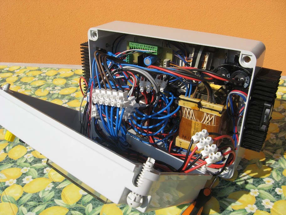
Rear panel power stage
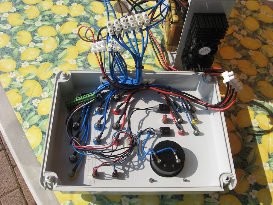
interior of the station by
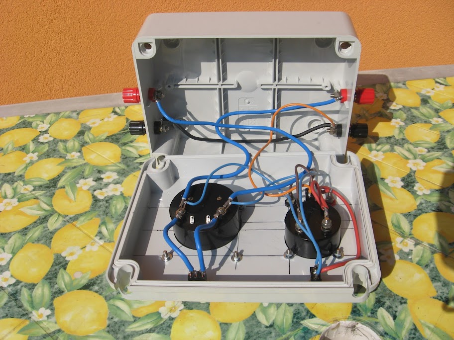
Internal Power stage
Link to all photos on Picasa supply (recommended): LINK
incoming schema
0 comments:
Post a Comment