Tuesday, May 27, 2008

Which Victoria Secrets Models Are Vegetarian

AMP6 and welds

and I 'happened by the hands amplifier ordered the now famous site www.41hz.com , in this case a model AMP6. A friend of mine had started to mount, but in pre-test some details not convinced, so I decided to "have a look." Point out that my friend is just beginning to experience something, to do some welding non-trivial to design and assemble a pretty good.
After a first review, in which I replaced a resistance that had been removed for purposes of measurement, I noticed some inaccuracies that now set before you. First
welds. I never try to write the myriad of links that can take you to the most 'different tutorial on welding (sorry, soldering) on \u200b\u200bthe pond, the type of pool to use the power of the welder, the paste flux or more' appropriate and so saying. I will just say that it takes "a good hand, a good eye and a good nose", as for all experiments in the field of electronics (and I confess that this maxim 'a friend of mine was told by repairman, meaning the good hand to be able to govern the soldering iron, good eye for not committing gross errors, and then the nose is understood as "unused" both in the literal sense, a nose that immediately feels any burning smell!).
Most of the welds were done properly, except for those on the ground floor. Probably the iron was not left long enough on the point to be heated, and the result was a welding surface, irregular, hemispherical shape, which, while ensuring continuity 'power, certainly would not hold the more' modest efforts mechanics. This is because 'the ground plane quickly dissipates heat from the soldering iron, and therefore requires more' time to make a proper weld.
I would say that you can 'categorize definitely in the category of "cold welding", that' those in which the temperature and 'was insufficient to complete merger and amalgamation of the pond and the flux.
Never mind, often enough to heat the soldering to see suck tin metal in the hole, and maybe does not hurt to add some more '.

Different situation for other welding on conventional runways. Here the problem was the excessive amount 'of tin found in some areas of welding, which necessitated the use of desoldering braid.

Judging by the color, the pond and used 'the classic 60/40 to 1 mm in diameter, that is well suited to the majority of the welds. Personally I have had better results using the pool 67/33, 0.5 mm in diameter. especially for SMD components. I noticed that this type of pool uses more 'time to cool down, perhaps because of the melting temperature significantly more' low compared to 60/40, more cooling 'slow and gradual' pay to avoid the occurrence of cracks in the material, which in the long run lead to a degradation of mechanical seal, to be avoided especially with the components' volume.
Welds with tin 67/33 are also noticeably more 'shiny, perhaps for the small amount' of silver in the mix, but this is not completely secure. I am going to try the other alloys, and to experiment in the lead-free soldering. A short
my impressions!

Tuesday, May 13, 2008

Mac Nc20 Is Revlon Colorstay

Linn Majik - The repair is complete!

I can finally write this sentence: I seasoned the Linn.

Today I finally bought the four resistance from 0.47 ohm that I needed to complete the work.
After change of resistors, a first test has confirmed the full functionality of the Linn, I then proceeded to thoroughly clean the last traces of paste printed on strong, and I stayed in his mobile electronics. The pictures tell a thousand words.


photos and final stage of power:


Photos overall electronics before putting in mobile


Photo Display (forgive the poor quality):


The back of the card. Note the tracks redone:


Photos Mobile


transformer and interface to the network:


electronics lies in the mobile


The rear panel, with the abundant range of inputs and outputs:


And here all components burned by lightning!


A sincere THANK YOU to Mauritius for the TDA1514 and the transistor!

Sunday, May 11, 2008

I Want To Made My Own Kundali

Linn Majik - The repair continues

since the last time I spoke of this repair has gone a bit 'of time, but then I forced myself to go more cautious than ever, given the fragility of the "patient" and, last but not least, the money invested.
Today I can finally say that most of the circuits "suspicious''work.
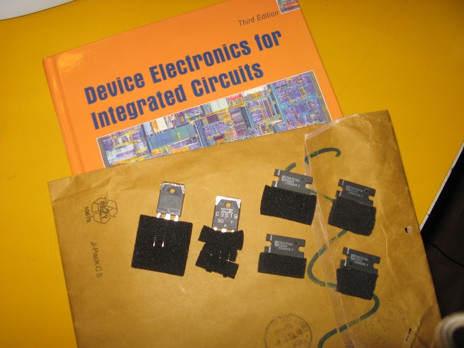
Everything went this weekend, after Thursday I received the registered letter containing the four TDA1514 and the two power transistors!

Here they are:


I must confess that before you turn on the welder and do everything I prayed for a long time not to see disappear in smoke the result of many hours of work .. But it was the only try.
I started with the replacement of the power transistors "hairpiece" (the BD249C and TIP145) with the "official". The 2SC3519 and 2SA1386 place. I shaped appropriately to fit the pin to the particular form of printed, as well as to rebuild a couple of tracks lifted. I can say today with a good approximation to the path of lightning: the cable is grounded and 'propagated through the mass of cross-gain stages, until reaching the final of the channel left, and that 'once burned. The right channel has suffered the same fate during the first switching amplifier, because of the damage to the power supply. Even the most 'robust chip would jump, with a' power in that state, went to the power transistors (the original 3519 short-circuited, the other open), the regulators do not regulate it, and who knows' such as short circuits, which do not I had not even bothered to verify because 'I was taken by the heat of unsolder everything' that seemed to''go.''
But now, with new parts in hand, and the tests done, I was more 'hopeful.
The replacement of the power transistors did not give me any particular concern, because the situation could only improve, because the transistors were precisely those for which the power supply was drawn.
fact, welds are completed, the tensions reflect faithfully those required: 26 volts on the positive branch and -25 on the negative. All right. Now we must be careful not to burn the transistor just posted, maybe with some careless maneuver!

thousand scruples before welding the precious TDA: schema
Before welding the TDA1514 was proper control, datasheet in hand, all the networks around the chips themselves, from inputs to outputs. The circuit is quite simple and repeated identically for the four chips, it behaves just like the classic "big op" then with the components on the input impedance, the feedback network, the capacitors on nutrition, and safety net SOAR. This last network was more complex than expected, given that the amplifier provides a function of "muting" automatic, as well 'muting a force derived from the jumper mentioned in previous posts.
Looking at the circuit, I noticed that on one hand the network of SOAR follows closely that of the sheets, with a 470K resistor to ground and a capacitor to the negative supply branch (in the datasheet from 3.3 uF, in Linn There are 22 uF!). The time constant of this RC network determines the time of "standby" mode before power amplifier complete.
internal comparators to 1514 mean that a capacitor discharge (0 ~ 0.9 V compared to the negative supply branch), the chip is off, then with a voltage between 2 and 4.5 volts
positions is in standby, and then finally with voltages between 6 and 7.25 volts is in full operation. The network
SOAR enslave the right channel was healthy, with the meter measuring the voltage on pin 3 of the pitch, could be switched from 0V to follow the trend (again with respect to-25V) rose slowly to reach the mass. The internal circuit TDA1514 limit the slope of the tension stop at the maximum value of about 7 volts seen before, so if in the measure could reach the power of mass (Ie 25 times the negative branch) at the end not attached to chip never climbed above 6.5 ~ 7V.

An unexpected failure
The branch that enslave the left channel but it was fixed at zero volts. Look carefully at the tracks that made up the branch, you could see those who were most damaged, a sign that lightning has struck with more force in that area. Something was definitely burned.
E 'needed was a measure with the tester to understand that the short circuit to 25V i-was dry. In fact, the 22 uF capacitor, once unsoldered, was in full short circuit.
Replace the condenser is a piece of cake you say, but where I find it a solid state capacitor 22uF 25V SMD? In my spare parts I did not, and even in the cards that I keep as a rich mine of SMD components.
I have noticed that capacitors like this one there was another trivial level that the voltage of 5 volts, placed in the stadium entrance. I have therefore taken the capacitor "good", I welded in place of the short, and in its place I put a 22uF electrolytic 25V I had at home, for the task that has to play it just fine!

Solved! It all turned
answered correctly, with displays that reacted promptly, and the voltages across the capacitors that came up as expected. MUTE jumper from the tensions down sharply to zero, the fire system went up slowly as it was reasonable to expect. Another problem solved!

Prudence is never enough: a test for all components
feedback resistors of the chips were all healthy, except for a 150 ohm which appeared healthy, but it was fixed with the solder (in fact they were a somewhat 'opaque), and appeared as a short circuit!
E 'enough to redo the welds and everything was fine.
For safety I also refreshed the welds of the other resistances, then made sure of their correct functioning. On balance, if the resistance of 150 ohms offending had acted as an open, on the TDA1514 would acted as a buffer, and the output voltage would be line level, so much more 'lower than that delivered by the''twin''and this would lead to a drastic drop in output power, which would be dissipated on resistors adaptation (and here 'cause I chose not to immediately put those to be 0.47 ohm!).

Offset adjustment
I also discovered the precise function of the two switches in the feedback network of a chip of the right channel and one for the left channel.
As I suspected, they serve to fix the exact value of the feedback resistors (this is a 500 ohm trimmer in series with the feedback resistance of 3.9 K) so as to ensure matching perfect gain between the stages that will end up in parallel.
For a measure with the meter, the series resistance and trimmer fit exactly as the resistance of the mirror stage: 3910 ohms in one stage and another 3915. Precise enough to make me seriously consider leaving them there, without even re-calibrate the system!

Schematics increasingly complex operational for temperature compensation
remained fairly smoky the role of two integrated dual op type TL072C, acting on the feedback of both stages. It seems that they are connected to the heat sink all'NTC fixed, presumably Then fit a network of temperature compensation. Their
operation seemed to adjust, there were no cortoocircuiti, and I'm not going into further investigations. Curiously, these two ICs are supplied to the voltage dual + and - 14V, obtained from 317-337 which generate the dual 15V, which are flanked by two medium power BJT SMD causing the fall of 1V, thus creating the 14 volt dual . Capacitors galore.
Perhaps you wanted to improve the decoupling between the power of the stadium entrance (the only one in fact to be fed to the + and - 15V) and the stage of temperature compensation.

The trick for the end of the parallel
short, everything seemed ready to host the TDA1514, but balancing the resistances of the outputs. Resistance from 0.47 ohm 5W I had already taken off, since they had "open" (always inevitable that headed to TDA as "damaged"), and the other I still want to change them.
decided, as mentioned, that for the first tests, I could use the four power resistors from 18 ohm 11W I had in my drawer.
In case of problems, I immediately felt the heat resistance, rather than the smell of burnt chips!

And so I began to pay off the first TDA1514.
decided to weld them one at a time and switch every time, trusting that in fact the four chips are operated by four separate circuits, and anyway even with a single chip amplifier should operate; at most, in the event of catastrophic failure, I would have sacrificed one of the four precious integrated.
After careful soldering of the pins, I checked the continuity 'of all the tracks and the correct correspondence with the function of each pin that was supposed to play.
seems okay.

TDA tried the first ...
Connect the power adapter and the display, and the heart pounding I put the plug. The processor reacts with a noticeable pulse, to load the big 10,000 uF capacitors. All quiet. After three seconds, switch off, and transistor chip key, all cold. Well, at least I can feel to exclude the possibility 'of a short circuit or faulty connections.
Connect a signal to the corresponding RCA CD input, speaker places a "laboratory", and turn again. All quiet, looks good half a minute with your fingers on the board for possible areas for potential to overheat, and I decided to start the music. It was so
'Radio Ga Ga''that''the Queen baptize' rebirth from the ashes of poor Linn Majik, which at this point could be considered on track for full recovery.
The music coming out of the box, the correct answer of the volume control and gearbox input confirm the full functioning of the entire circuit. Much of the doubts have been dispelled.

The road is plain
Proceed with the same task with only one chip to another channel.
With a thousand heart always light it up, and I can finally enjoy the sound in stereo!
All quiet even with the temperatures, everything gets hot to the touch but evenly and''normal''.
Taken with joy to see that everything is working fine balance of the third chip, and then the fourth.
After checking in obsessive detail do 'tension, and finally everything works as it should. All 4 chips work together, Radio Ga Ga comes out clean from the speakers (though they may be laboratory, they sound just fine! Or maybe it's the quality of the Linn me to hear music so beautiful or maybe my satisfaction?).
reached this point, a nice break and a good coffee 'is a must.

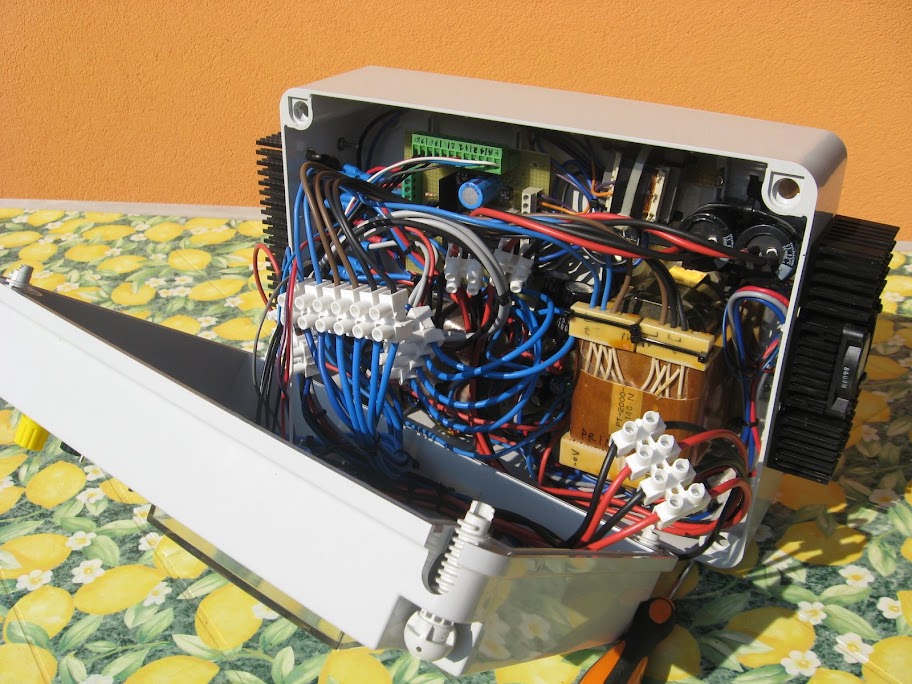
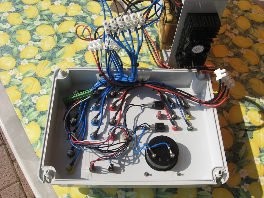
Joking aside, here is a photo caption of the work in the current state of things in more detail about Picasa
Visible: 
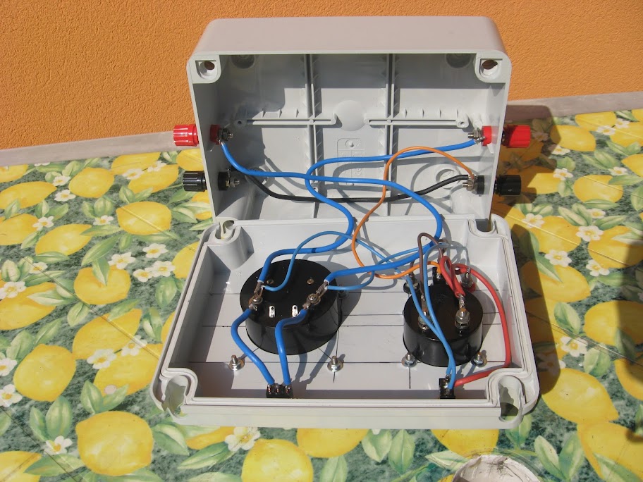
LINK


A curious cooling system
Note the small size of ' heatsink, anodized aluminum. The anodized aluminum makes electrically insulating, and in fact during the disassembly of the amplifier I have not noticed any mica insulation, and even a little 'white paste. To do a more thorough job then I proceeded to fix chips and transistors with good chemical and insulating silicone a fair amount of thermal paste.
During the tests the flap (if you can call it) has reached temperatures high enough to touch. Evidently
heat dissipation will be more efficient with the amplifier in its metal case (aluminum is, and quite often), to which the flap will transmit the heat. However, a choice really ingenious!

Wednesday, May 7, 2008

Breast Enlarging By Diane35

feeder bench

description of the project is finally perhaps the most 'controversial among fans of electronics: the' power supply for your lab bench. He was born
My idea discussed a little '(animated) with colleagues at the university', in relation to the device''ideal'' that would solve all the possible needs for food laboratory. At some point we created two lines of thought: those who said that power supply should be minimal, with only one adjustable output and''perfect'', and those who said that the panel had to find alternate space in all outputs, all the fixed voltages of 1.5, 3, 6, 9, 12, 15V, and at least two output variables, and of course strictly analog instruments.

was at that point I thought: Why 'does not achieve a modular structure, to dial as needed? In the end, a super-power-equipped as I can 'be exploited? Almost never!
I decided to divide the concept of''power'' into four basic sections: the section of raw power (transformer, bridge and capacitor), the regulator, the instruments and the Security section.
I decided it would be a good idea to make the individual units 'in separate boxes, to be connected as needed in order to make the structure flexible, besides' cleanest possible, since every time you are connected only with the combined 'you want.
confess that the idea came to me looking at the quantity 'industrial bushes and banana plugs that I bought last year at the Fiera di Pordenone, and which had remained unused for a long, long time .. It would be a shame not to use them, right?

was so 'that I began to realize the bank instruments, by enclosing it in a box model GEWISS 207.
These boxes are really ideal for prototype development and hobbies, plastic and 'great, it lets you work well and is' very strong, and also the bottom of the boxes and' full of ribs, good for fixing metal towers, transformers and everything 'else. In
''207''found space in a DC voltmeter and an ammeter fs 30V DC 3A fs, strictly analog, managed through a switching system that allows you to exclude the instruments (for more tests' at risk for their safety '!), to report the measures to a different mass, etc. .. The instrument and 'very versatile and I use it virtually forever.


The second unit, 'I realized that embraces the "brute power'', ie transformers, capacitors and bridges. Since these components much more' bulky, I used a box model GEWISS 209.


Initially I wanted to include only the components mentioned above, but then, given the abundance of space, I added a bit 'of''optional'', which now list:
-voltage network to 220 volts is sent through transformers to the relay ', operated by switches on the panel operating at 12 volts. I did not like the idea of \u200b\u200bhaving the 220 volt panel, And then I can always predict the activation of the relay 'on a remote, or automatic, although I have not yet implemented this function, relay and' master / slave only to the switches on the panel. A
-10W 12V transformer provides power for the vehicle mentioned above, and the LEDs that I'm going to put on the panel (still remains an intention, given the short time available).
-The main power transformer and 'was recovered from a plotter, and' has a primary dial 110-200-220-240V, and three secondary, and with 220 to provide primary, respectively, the AC voltages of 9, 18 and 27V.
-I initially thought of bringing only the winding 220 mostly primary, but then I thought of putting a 3-position switch, to choose whether to keep the processor off, whether to send the 220V winding winding''220''or''240'', so tensions have significantly more 'lower than nominal. This is me and 'useful for testing the behavior of the load for example in the case of low voltage, or to verify the autosuscettibilita' of a converter. In short, the difference between the voltages obtained at the secondary and not 'high, but it can' be helpful.
terminals of the three secondary windings of this transformer are brought directly to the front panel.
-I then mounted a second transformer, a toroidal 50W with 20V output 20 + central zero. The output in AC and 'brought to the front panel with three terminals, which should ever try a dual power supply.
-This second processor in addition to providing these tensions to the front panel, dual DC power internally at least a full, made a pair of regulators LM317-LM337. The output voltages range from 1.25 to about 25 volts for the positive branch, and from -1.25 to-25V for the negative branch, and are regulated separately by two excellent panel potentiometers. The maximum current of 1.25A for each branch and 'more' than enough food for the majority of projects that require single or dual power. Then taking the tension between the branch with positive and negative, can be get too high voltages up to 50V, a voltage outside the normal range of common bench power supplies, which almost always arrive up to 30 volts.
The regulators are attached to a heat sink on the right side of the''209''. On the left side
-mounted sink another two bridge rectifiers 50A, accompanied by a 10,000 uF 50V electrolytic capacitors, good quality '. The inputs and outputs of the bridges across the capacitors are available on the panel, ready to be connected to any load and any secondary winding. Since all systems electrically isolated, and 'possible mass systems separate, or parallel to obtain the most current' high (perhaps playing with the windings secondary, but fatalistic 'supply voltages can easily be combined). On
-panel also includes a voltmeter analog AC 30V fs, very useful to check the actual value of the AC voltage to the secondary processors, especially under stress. No fan
-active, only external heat sinks and oversized, guaranteeing silence and reliability '.


An abundant supply of banana sockets on the front panel provides maximum flexibility 'in this box''power'', and permanent links (such as links between the transformer windings) can be realized with the common thread, simply by screwing the terminals of the Banana. Simple and flexible.
Each transformer 'enslaved by a switch controlled by a relay' on the side there is' a double pole switch, and last but not least I found room for an EMI filter to the line 220, which never hurts. The third

''box''that I made (specifically in a model GEWISS''208'') is not part of the power supply, but it 's an active load, I will describe' in detail in another article.

Photo details:
Glimpse inside the power stage (wiring)
Rear panel power stage
interior of the station by
Internal Power stage

Link to all photos on Picasa supply (recommended): LINK

incoming schema

Friday, May 2, 2008

Michelle Keegan Underrwear

T-AMP - and was AMP32.

As already introduced in the previous article, I explain how it ended experience with the T-AMP. The site
www.41hz.com seemed very attractive now, given the variety of kits available and the care with which the site is achieved.

The temptation was to immediately order a stop only embarrassment in choosing which kit to try, they all looked very good.
My choice fell on two kits: the AMP32, based on the TA2021 chip (2 x 15W RMS) and AMP4 (based on a complete chipset, can provide a power of 2 x 30W RMS). The AMP32
I was particularly attracted by the components, all in SMD, but very thorough. It 'was an opportunity to be expert in soldering SMD and appreciate at the same time a more substantial power from the famous T-class (let's face it, with 8 + 8W did not feel much ..!).

Assembly dell'AMP32 was not just immediate. Once learned soldering SMD components on two terminals then all look alike, and you can refine the technique using less tin, resulting in a good and satisfactory welding.
More difficult is the welding of the TA2021 chip. The SMD package is very thorough, the pins are very thin and very close together. After a disappointing attempt to weld "wave", I adapted to weld the pins one by one, removing any residue at the end of the pond between pin and pin.

The first time I have not been satisfactorily resolved: the amplifier will sound crisp and off after a few seconds of crackling and rustling.
First I rehearsed all welding components, allowing for final consideration on each chip. Having then established that the situation did not change, I decided to redo the welds of the chip, a task far more difficult to view the population of the board.
After two "past" of a welder here is that everything was functioning properly, and AMP32 still plays on my desk from time to time. Oh yes, because the poor amp still needs a "home". But that's another story. The AMP4
waits for his master has time to get to assemble ..

3 Dongle Hackers China

T-AMP - Every saga has a beginning always

finally write my impressions about the famous amplifiers in class T, which became famous thanks to the temporary fashion T-AMP, the 8 + 8 watt amp called the "giant-killing", "David against Goliath "and other picturesque epithet. This is an improvement in a few words of dell'arcinota Class D amplification in the world, in the class T is the carrier frequencies high order of MHz, and the non-ideal amplifier are corrected with a powerful DSP. The chip with which the fashion was launched was TA2024, which provides, as mentioned, a power of 8 watts RMS per channel.

The first experience with the T-AMP occurred within the MT-lab ( www.mt-lab.org Take a tour!), Thanks to our friend who has brought the legendary "Sonic Impact for some proof.
The first listening tests were quite positive, but we wanted to be more daring. Now we have disassembled the amp in question, place it in a most practical mobile technology and make some improvements (more powerful power supply, replacement of a component, etc. ..). The results were there, but during testing the T-AMP decided to leave this world .. Any comment on that experience can be found at www.mt-lab.org .

After several months of disappointing, albeit interesting, experience with the TA2024, I decided to search the net a late replacement for the amplifier, and landed at the site www.41hz.com ...