Sunday, October 26, 2008

Is Susten 200 Capsules Good For Pregnancy

Repair (obviously electronics) a washing machine! Final

I recently had the opportunity to "get their hands" (for the umpteenth time, to tell the truth!) In washing machine at home.
Suddenly, the dear washing machine did not want to learn to spin, greatly complicating the operations of drying clothes (this time then!).

Needless to say, in a time of five minutes the machine was carefully dismantled to find the cause.
So ... If the spin does not start, or is the engine, or are the brushes, or is it .. ECU!


's think logically.
The engine seemed in good condition, no signs of burning, no funny smell, no suspicious noise, maybe just the brushes a bit 'worn, but could still do a lot of "road".
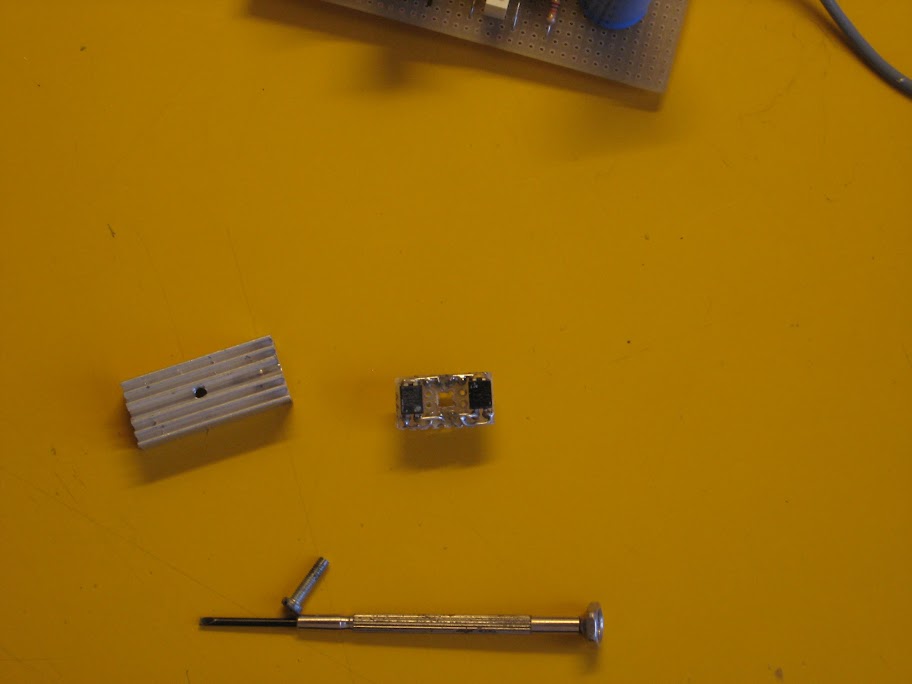
E 'Simply remove the unit from the narrow slot (some sources confirm to me that there are teams of people devoted to studying the most uncomfortable position and unreachable for these units blessed!) to realize the problem.


Diagnosis of the fault.
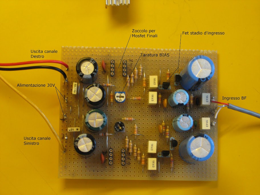
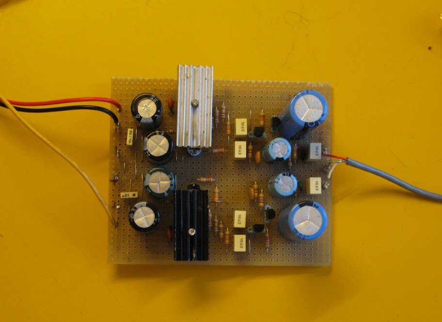
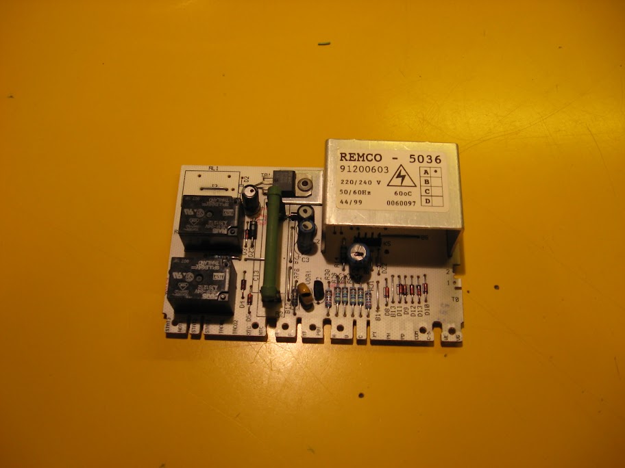
An overview of the upper side usually allows you to find components visibly burned, damaged or even explode, but it is not 'the case.
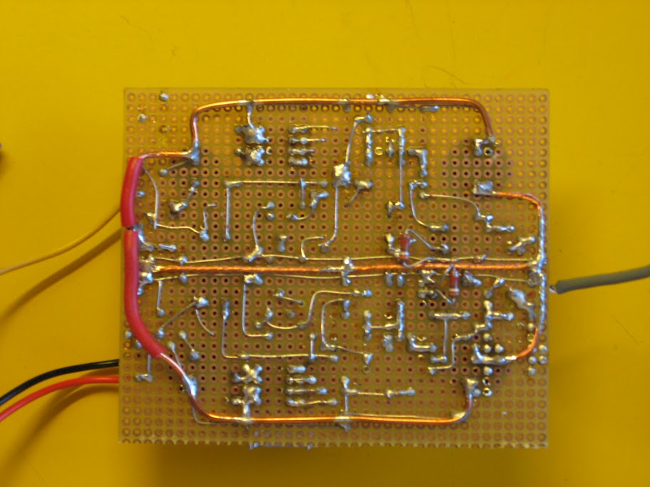
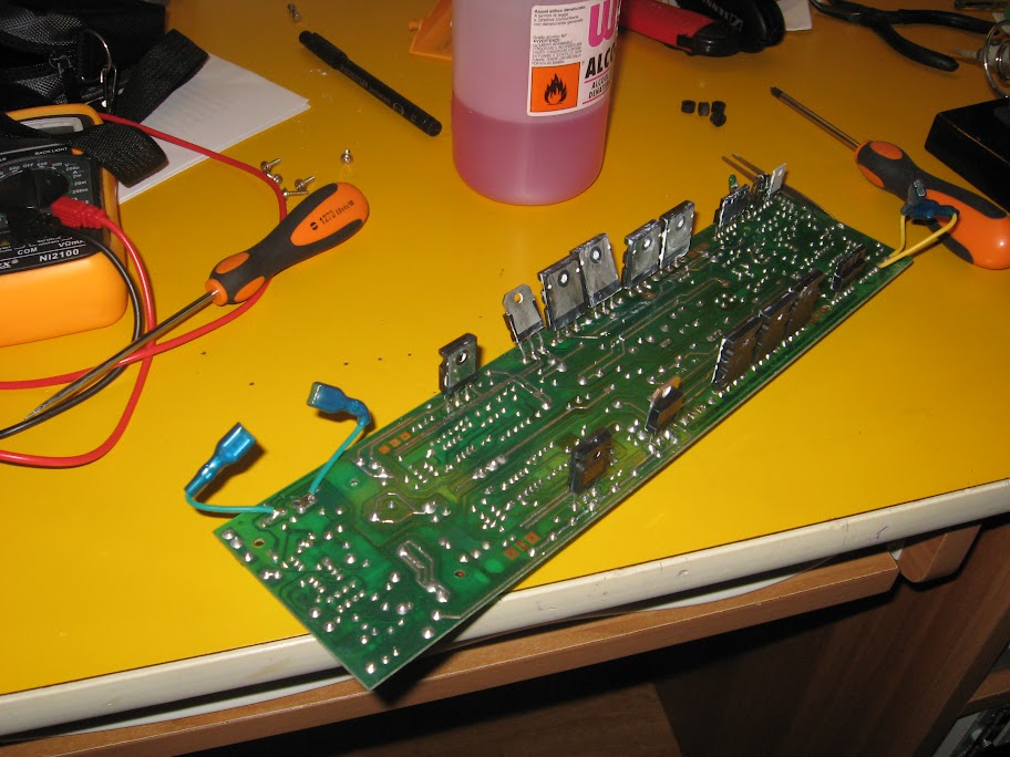
Turning the card looks pretty clear the source of the problem:


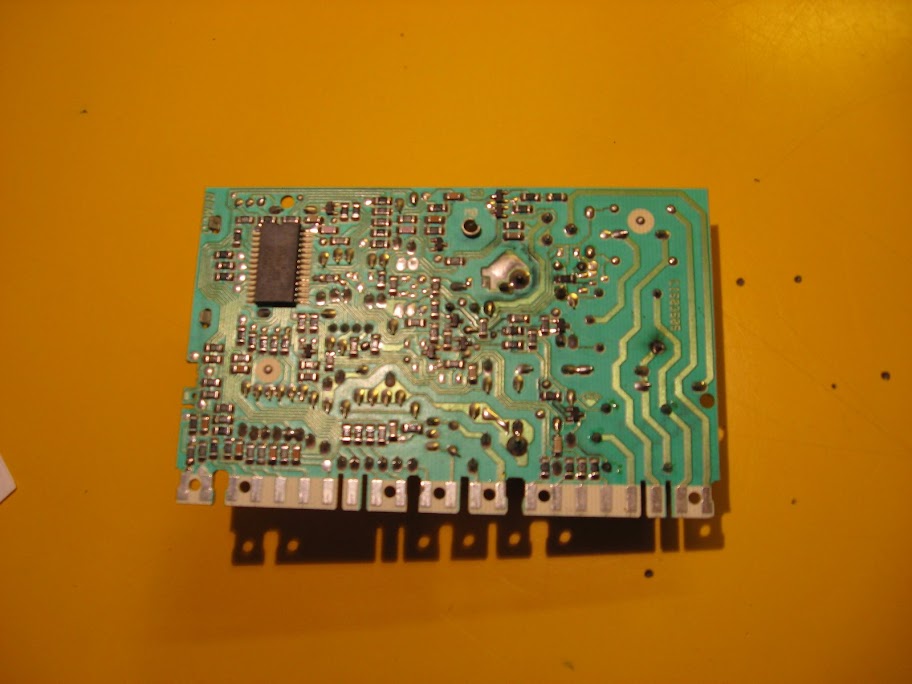
not noticed anything? Not even on the right?
closer look:


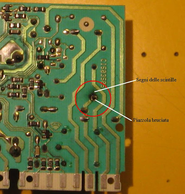
Oh yes, you as well! In correspondence with one of two relays visible in first photo, there is what remains of a weld. The pitch is gone, the pin of the relay charred, and instead of the pond there is a black flash.

The fault of this card is due in all probability 'the combination of mechanical stress, humidity and general poor quality of the printed circuit board. There is in fact saying that the other welds did not look good, and the severance of this specific welding prelude to future failures of the same type.
happens that a weld is deteriorating as a result of mechanical stress (such as vibration or temperature changes), giving rise to the same flaws, which undermine conductivity. The current (rather high in this case, since it is the relay of the centrifuge) does the rest, warming and deteriorating further welding, to lead to sparks that consume in a short time.


how to proceed.
The repair of this type of problem is obviously to restore the original welding, but necessitates a review of the entire printed circuit board, to counter the possibility that the failure is repeated (very probable, with circuits like this bad).

First you have to clean up the damaged area of \u200b\u200bdebris, burning marks and dust and to this end is fine a bit 'of sandpaper Very fine. Here come the first problems due to heat.
In this specific case, the heat has altered the protective coating of the PCB, which in fact is scraped up adjacent to the welding of the relay. The copper track and 'almost always compromise, and we need a' tin 'of the track itself, ie the deposition of a thin layer of tin, which provides better conductivity and mechanical strength.

After an initial mechanical cleaning, is necessary to act with an alcohol-based rinse and thorough drying. Particular attention must be paid in the peeling of the runway next to the weld (which will serve as support). It often happens that it remains a bit 'of welding and paint the border of the track, effectively creating a barrier to future welding 'cordon'. should operate with an awl or a knife to free any remaining copper.

Given the conditions affected the runway and the terminal of the relay, you should not skimp with the flux. Personally, I pre-tin the end of the relay and the track, the entire applicant pool that I needed, and then I acted with the flux, which has greatly helped the distribution of the pond. The pond is used
the 67/33 already presented above, I chose this pond for his skills as a greater flexibility in cold, and the best quality of the internal flux, which is essential for this repair.
After the first layer of tin, have strengthened the cordon with another pass.
is the result:


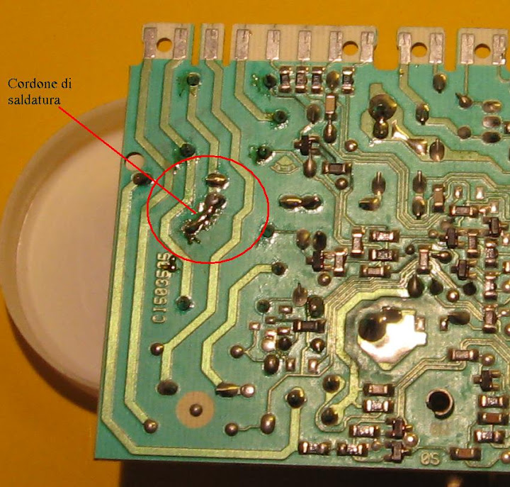
You notice the cord now connects the terminal of the relay closest to the pitch. The slope of the underlying copper is in fact only as a guide, because its strength has been hopelessly compromised by the heat.


considerations.
After fixing this welding, I refreshed many of the other, sometimes adding a little 'tin, sometimes working only with the flux and adding very small quantities of tin. We must avoid it in the strongest terms of 'weighting' stir welds mildly tin old to the new one, as the amalgam uneven and 'practically a guarantee of failure (and' a sufficient temperature change for 'cracked' inside the tubes), and the addition of tin easily causes a swelling of the weld itself, which directly affects the mechanical strength.

welds are to be reviewed especially those relating to the components Through-Hole (TH) with bent pins. Looking at the photos carefully before you notice in fact some components with bent pins on the PCB before soldering.
This usually ensures a better mechanical strength, even when the seal is made of great economy. Some
pin, as precisely those of the relay, can not be folded (they are too short and their splitting would lead to a greater section rather than a bending), and are therefore more susceptible to failure as the one being analyzed.

After cleaning the room unit (collcato down, right to protect the electronics from the steam) and re-assembling the machine, everything worked again, better than ere!

All photos are visible at full resolution on PICASA .

Saturday, September 20, 2008

Confidentality Agreement

LX1444 headset ... Amended! DAP Audio

Taking advantage of a short break from studying, I started a project that I started almost a year ago.
This is a headphone amp, I wanted to finally connect to my computer.
almost always listening to the audio in the headphones, I immediately felt the limits of my sound card, both in terms of power output of that band. Low frequencies, in particular, were reproduced with difficulty, and indeed it must be said that the final stage of my "Creative Sound Blaster Live! OEMs" was not exactly designed to drive headphones from 40 ohms (which are mine) , and it was inevitable that such a low impedance strongly influence the dynamic qualities of the card.
I am not aware of the value of output impedance of the board, but it is likely that this is high output impedance.

The choice of the final.
I analyzed a number, because I could use the integrated end-type LM386 or TDA2822M in my possession, I could make a simple buffer BJT, and I even considered a tube glides by new electronics.

Given the cost of that alternative (out of my "budget"), I headed to another kit of the same journal, signed LX1144 (available in the magazine No. 167-168).

This is a final 1 + 1W RMS input FET and MOSFET final, a very elegant solution. The characteristics of "plate" are very attractive, and one can easily obtain a gain of 30 dB.


construction. Kit or spacers?
After I informed, and have gathered opinions uniformly favorable to the kit in question, I decided that I would have built.

However, as I was going to change it, would not make sense to order the complete kit, already had all the components, and my changes would upset the PCB, with unpredictable outcomes. The printed circuit board provided in the kit is in fact equipped with a ground plane, which provides excellent immunity to disturbances, but restricts the possibilities of change. I then collected

all the necessary components, and armed with the proverbial breadboard, I replicated the circuit as it was proposed in the magazine.

Although some details changed immediately went, I also tried this configuration "base" and the result proved to expectations.

A sound clearly different from the "tired" that I used to listen to, the headphones were now being driven by a decision even in the deeper bass while maintaining a more than ample bandwidth (the data indicate a band of 20 to 22,000 Hz, + / - 1 dB!).

While not using a print screen to the ground plane, I have picked up disturbances, except maybe the signal from the phone close by and the use of a matrix board also has its limits!


limits and changes
preplessità My only at this point concerned the weak points "known" in this kit.

First, the endings are made with a pair of complementary MOSFET signed IRFD.1Z3 IRFD.9110 and in HD-1 package, much like a four-pin DIP. New Electronics designers have brilliantly solved the problem of the plinth using a 8-pin DIP socket, which accommodate the P-MOS and N-MOS of each final. This solution, although avoids direct soldering of the FET, it has some limitations. First, it becomes difficult to establish

qualsiati type of heat sink, less than "paste" directly to the finals, also, given the nature of "snap" of the hoof, there is the possibility that the transistor over time become detached from their place, with Results imagine.

Then, even wanting to use a heat sink attached externally to the mold, it collides with the filter capacitors, and with the same problem of 'instability' of the MOSFET on the hoof. It is not appropriate to apply any pressure to the whole "Mosfet + socket," not to bend any pins. In short, you have to work with the MOSFET not dissipated, and, with the currents involved, these components tend to heat up considerably.


I then placed the MOSFET in a slightly different way, by welding on a support floor, and providing a heat sink. The images easily explained as I did.

The amp is still at the prototype stage, heat sinks are still too close to the capacitors, but with a few more I'll take it arises to change all'assetto final. Here are the results so far:


amplifier without the output transistors. Hooves are visible: Used


The amplifier in the final in their place:


The back of the end. You can see the tracks of large mass (middle), and the two runs for the 30V (which extend to the sides). I made these tracks with copper more often in order to ensure maximum readiness in the current peaks.


An overview of the technique used to mount the transistors on a removable medium and strong. Magnifying the image is easily seen the "trick".


All images can be viewed at full resolution on PICASA .

Monday, August 25, 2008

Good Value Teck Decks

P2000 Vintage

Recently I was able to complete the repair of a genuine "Monster." Two-channel 750W RMS each. Stuff to festival, as they say in my part.
The patient in question, as the title, an amplifier of DAP Audio Palladium Model 2000 "Vintage". I had already heard of the DAP, with regard to professional power equipment, and in fact the module in question has all the features of the case and is mounted in the rack.
But let's go. The owner of the amplifier, an acquaintance of mine who owns an audio-video service, told me about the dilemma on a night, the right channel was blown improssivamente, and gave the panel "in protection." Amplifier open, you immediately noticed the fuses 12A burned.
The replacement of the same caused the melting of the fuses again, a sign indicative of a short circuit quite dry. The amplifier open

:


As soon as I heard the description of the fault, I did give the amp to have a look, thinking quickly to a short dry in the final stage, a problem quite common in amplifiers Class AB; certainly did not expect an ending so powerful.
Four pairs (per channel!) 2SA1943-2SC5200 transistors complementary, couple that I found to be widely used in audio.

The transistors:


The discovery of the fault
I then removed the damaged module on the channel, marking the layout of the wiring (there are several, at least fifteen Faston connectors, power cords with a silicone sheath, a real delicacy). By measuring with the tester gently
the presence of shorts, I noticed the short dry downstream of the fuses, almost certainly due to some transistors in the final went the full circuit.
The only way to ensure that this was unsolder all the endings, and check them one by one.

The private channel heat sink, the transistor should be noted:


In fact, after a simple measure of continuity tester, I found a shorted 2SC5200 and 2SA1943 dry. I felt that the only cause of failure were the two transistor amplifier, and proof of what I resolder the remaining working, I reinstalled the whole thoroughly, and the final work again!
In my opinion, the transistors are blown to overheating, and you may at first only one of them is gone short circuit, the potential tying the output power (positive or negative), leading to clear the merger of one of transistor of the opposite line. This chain reaction has caused a short circuit at full power, which melted the fuse and stopped the imminent complete destruction of the finale.
For the first experiments I used cautiously fuses by 3.15 A.

The problem of transistor
The problem at this point was to find new 2SA1943 and 2SC5200.
suppliers via the internet is better not to speak, I found sites very "shady" with shipping very smoky, and sites that did not send until my next order (I do not do names for obvious reasons, but because they have only lost long time and obtained more discourteous responses)!
short, if one needs a 2SA1943 and 2SC5200 can not have them, unless you pay them in rough diamonds or gold. Apart from jokes, I was genuinely appalled by the difficulty of find these transistors.

solution
Luckily I came back to mind the one who gave me the TDA1514 unavailable for the Linn Majik (see previous posts).
After a brief exchange of mail (which I also explained the trick is to read the code of "rank" to identify the range of gain hfe of the transistor), my "supplier" has got to go to Beijing (sic ) and find a pair of transistors exactly the same as mine.
In fact, the alternatives were searching for transistor rank "or", or the replacement of all transistors to ensure the proper balance of earnings, but the amount to be spent would be much higher. And then it was a pity 6 fully functional transistor unsolder and original because of two burnt.

Reconstruction ...
I then received the two new transistor, but before I had to assemble and disassemble and clean the sink all transistors attached to his body, since the thermal paste had dried easily during disassembly, and possible reuse of the same could seriously endanger the integrity of the amplifier.
In fact, the common "white dough" is not reusable because of dry (it takes just once air) produces the exact opposite effect to the warming, which isolates the transistors from the heat sink, causing, cone is imagine, the rupture due to overheating.

The probable cause of the failure
After cleaning with alcohol the sink, I noticed the details that made me seriously doubt the build quality of this amplifier.
The aluminum heat sink was particularly rough, you could see some holes and flared badly redone, a glaring sign of a machine tool that had lined aluminum own at the final transistors, evidently no one had thought to sand the area so sensitive, and insisted that the chemical transistors on an area full of valleys and burrs!
I then proceeded to rub the sensitive areas with fine sandpaper, eliminating any surface irregularities and ensuring a more dignified end to a 750W. I find it very strange that no effect was found of such basic quality standards.
The question has become even more fierce when I observed the thermal coupling of a pair of diodes and a thermistor. The diodes are simply supported aluminum, and held together by a thick layer of white paste, and the thermistor is literally "drowned" in a valley filled with the same dough.
Needless to say that with time the dough will dry up, and changes in temperature sensitive components such as diodes and a thermistor will work badly.
Anyway, I reassembled everything exactly "as it was before," without making any changes.

The amplifier is playing very well on my desk, but is driving the speaker 15W, so it's essentially "resting." As soon as possible will be delivered to its rightful owner, and I hope to be able to hear during testing at full power!
Soon more pictures of their work.

As always, the photos are visible in high resolution on PICASA

Once again, THANK Maurizio!