I recently had the opportunity to work for the first time on an electronic welder. I must say that it 'was very interesting, especially for the satisfaction in having seen "live" the things I studied at the University. I do not happen every day to see a circuit capable of delivering fifty times with nearly two hundred amperes of current!
Here is a picture of the "patient" before the repair:
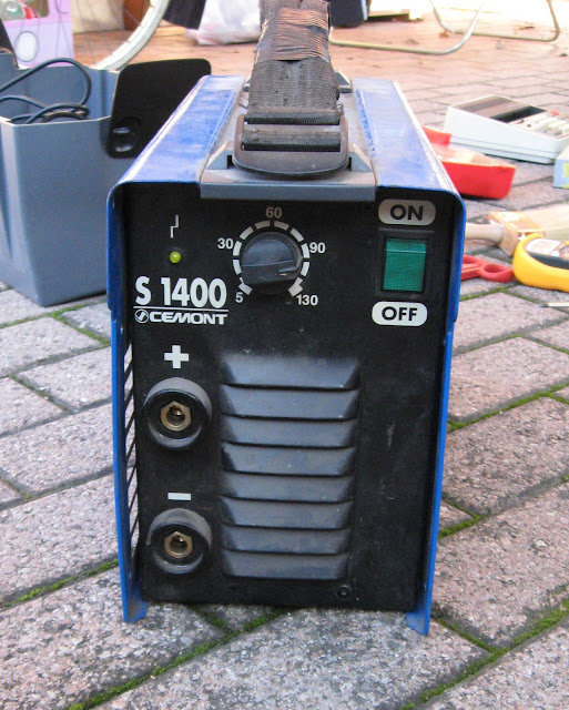
After a rather intense period of operation, the welder has simply stopped working. And not 'more heated, I' the light on the panel has more 'showed signs of life, even the fan is stopped.
Open the welder.
Needless to say, I opened suddenly poor welding, chasing a failure!
The first step when you examine the inside of an electronic device and 'identify the basic components, imagining a possible block diagram.
first assumptions are often wrong, but careful observation and 'essential to decide what to do.
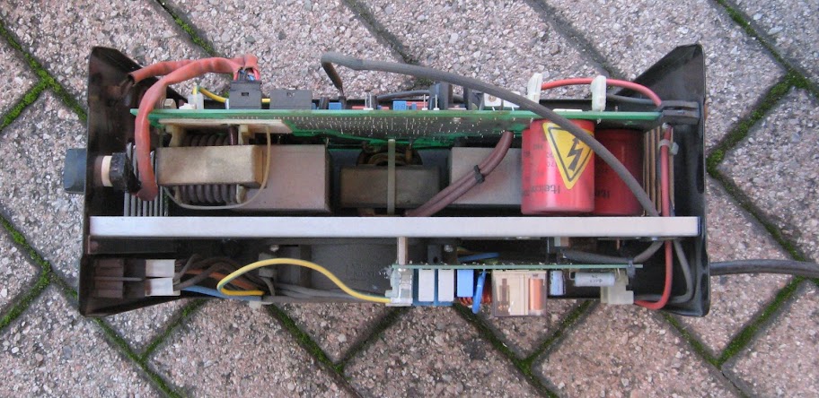
The interior side of the Fan:
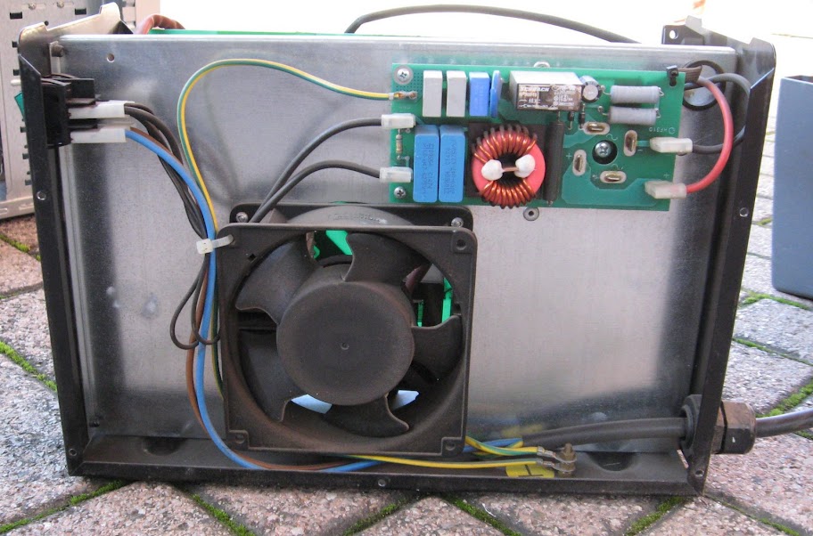
From this perspective one can 'follow the path of the power cord, passing through the switch, the gate voltage to the first small board. in all probability 'is the filter feeding, omnipresent in the circuit-switched, looking closely you can ' guess the structure of the filter formed by capacitors, polyester and double inductance clearly visible in the center. The block diagram of a filter of this type, 'this:
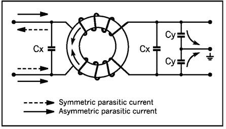
Capacitors help filter out high frequency disturbances, especially those made by the welder, while the inductance helps filter out the component of common mode current, always in high frequency.
One disadvantage of circuit switching consists in the generation of several harmonics of the disorder.
A filter, even if rudimentary as the one in question, it is essential to not overly stress the components of the electricity grid.
On the right side of the board, mounted at the rear, and 'guess the placement of the large bridge rectifier, from where the red and black wires to the main board.
protection system against overheating and 'very elementary. The resistance wire inductance can see next provides power to a secondary circuit present on the main board. By processing the signal from the thermocouple mounted on the heatsink, does energize the relay 'in case of overheating . Typically this is an amplifier followed by a comparator to trigger of Schmitt .
cables for power and control signals are contained in the pocket, sterling black, best seen in this photo together with the thermocouple (mounted on the aluminum plate in the rear):
 click to enlarge
 always show the same picture can be seen on the filter capacitors (red).
Let us look at the main board:
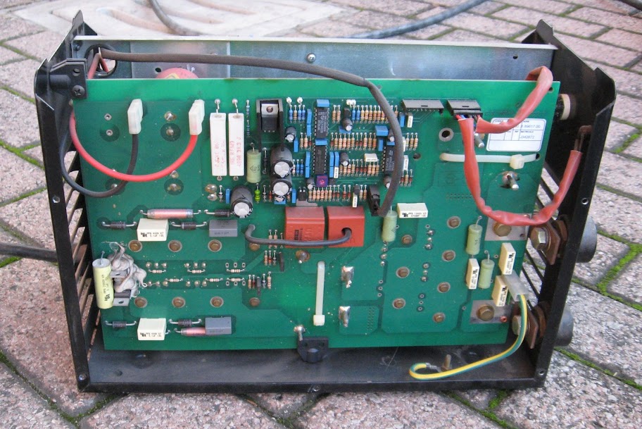
We note immediately rather intuitive layout of the components. The mains voltage is rectified previously leveled electrolytic capacitors in the picture above, and the DC voltage of about 320V so 'obtained is sent to the stage (and here' mounted behind the printed, covered by heavy cooling fins).
The finish seems to be of dual - forward, given the presence of an isolating transformer windings for simple (a single primary winding and a secondary recirculation diodes , no center tap), but I found more information in merit. It matters little, since the problem was somewhere else.
fact, is derived from previously obtained immediately 320V power supply for the control stage. Looking at the top of the tab, you can 'see a governor in a container TO 220 (in this case a LM 7815), and several other capacitors leveling, as well as two large wire resistance, which have been aroused my suspicion.
The first thing I did after having opened, reviewed and cleaned up the welder and 'the measure was "hot" stress more' important.
WARNING: The test 'was carried out with fully open and welding voltage mode. How 'reported on the carcass of any electronic device, any measure should never be done in this way, but respecting the minimum precautions I decided to take a chance.
It goes without saying 'that's inexperience, haste and lack of knowledge of the internal electronics are factors that require immediate closing and that the delivery to the repairer as' trusted.
I started the measure starting from the filter capacitors, and verifying the actual presence of continuous 320V. It must be said that the bridge rectifiers and are always slightly oversized and rarely undergo failure.
I then shifted the focus on nutrition monitoring, starting from the controller.
E 'soon became clear that the 7815 does not pay any tension between the central terminal and the output terminal (easily identifiable by datasheet ). Not even the upstream voltage regulator showed signs of life. Evidently the problem was before, and indeed the two-wire resistance revealed the secret.
To the leaders of most resistance 'to the regulator fell near zero volts, while the other heads I measured the famous 320V!
At this point it was quite desirable that the resistance was broken, and in fact the measure has proved me right.
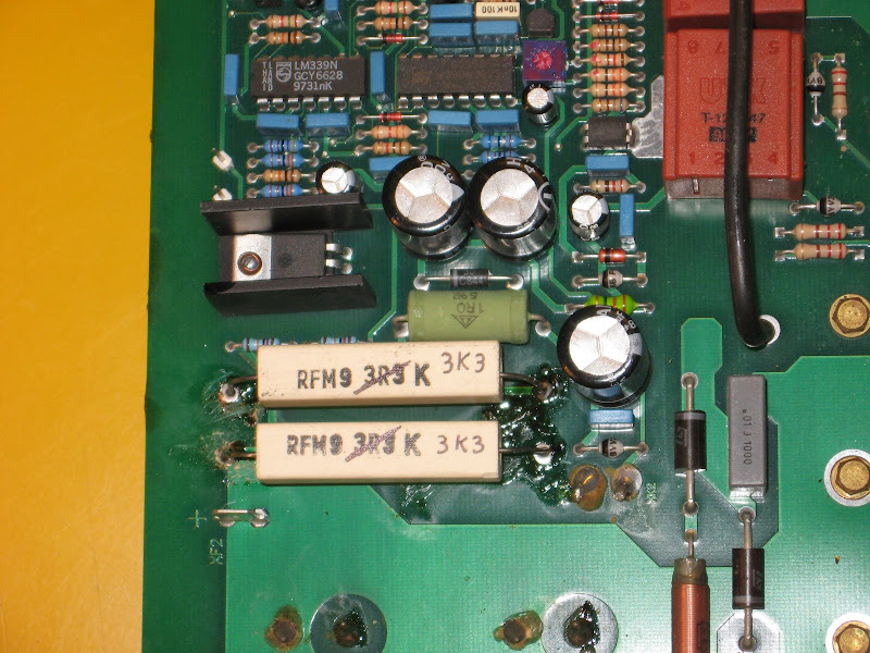
you look closely you can see the photo already cut the legs of the resistance (cutting and 'need to get a reliable measure of resistance, do not forget watch out!). One was still healthy, the other, as expected, lost.
repair.
I immediately searched the resistance wire identical to the originals, but in addition to having experienced significant difficulties to find it, I was not totally happy with your purchase, simply say that I bought four replacement heaters at a shopkeeper who was fortunately provided, and one of them (certainly not the fault of poor seller!) Was already 'lost. .. Quality 'zero.
Here is a picture of the original strength, open to verify the fault, and that "new," interrupted
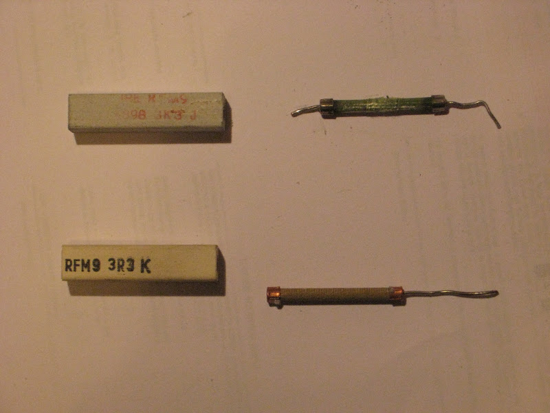
The original strength and 'up, its a full compromise does not need words.
acquired resistance, below, presents the filament slightly loose in the center, a sure sign of a break. Even with a measure clarifying the meter gave an interesting result: from one end and sliding one of the two leads to the other, the measured resistance rose linearly to about 1.5 Kohm , only to meet the ' interruption.
The issue of the abbreviation.
Looking carefully at the picture, there is an apparent inconsistency between the symbols of resistance. Look at them closely:
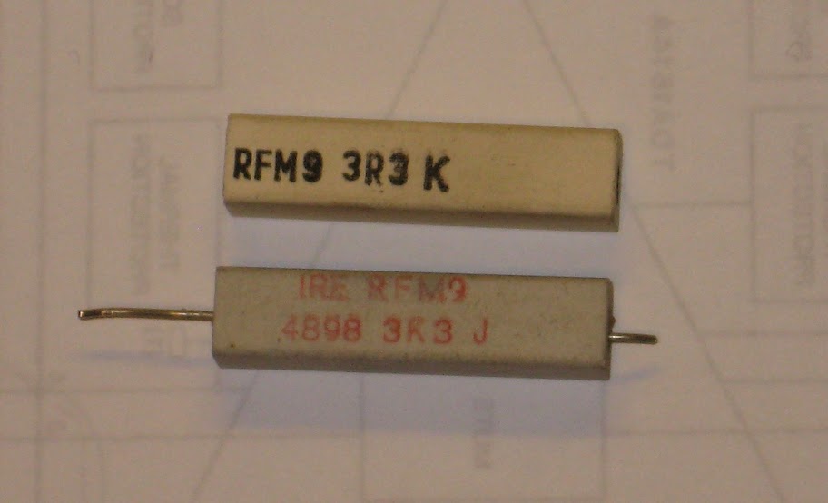
resistance originally stated the letters J 3K3, namely 3.3 Kohm 5%, 9W power.
The new one shows just the initials 3R3 K. Now, until proven otherwise, identifies 3R3 a resistance of 3.3 ohms, and 3.3 Kohm .
According to the seller, the "K" would identify the multiplication by 1000, but we all know that the letter after the code identifies the tolerance. Otherwise how to identify this parameter? Let
also the standard code (borrowed from another site):

We note that the "K" indicates a tolerance of 10%, while the "J", found on the original strength, indicates a 5% .
Not only does the resistance have a new acronym ambiguous and one in four and 'bad, but also have a high tolerance more!
In my opinion it is a gross lack of production.
It remains an open question on the code, I invite readers to give their opinion!
However, given the reduced critical component in this specific application, and given the difficulty of finding them, I decided to also finish the repair.
I then proceeded with the cleaning of the weld with flux solid and desoldering braid. The welding of new resistances took much time because of the need 'to heat the large mass of track on which he insisted one of the leads.
warming estimate (made by simply taking the 50W soldering iron for about twenty seconds on the card, moving it from time to time) and it 'was necessary to ensure a reliable weld. Otherwise we would have obtained the most welding classic "cold", and the adhesion of the pond would have been very very weak.
I took advantage to also to brush the welds of the capacitors.
assembly and testing.
Here is a detailed picture of the area after the repair:
I considered appropriate rebadged resistance in case of future repairs. Not having anything better, I used a permanent marker fine tip, hoping it will not discolor. It would be rather sad if, in the distant future, a repairman had to make my own operation, and replace the burned resistors with resistance of 3.3 Ohm ...
is worth a look also to the first "heavy" of the circuit:
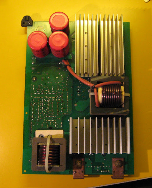
Fascinating, right? I must say the quality general assembly and 'definitely above average, and the precision of puncture and alignments, and' very high. The eye
note several important measures in the printed circuit board, such as the ground plane and the bolting of busbars flanked to the riveting, in order to ensure optimal electrical contact.
exception, I have decided not to clean up the welding with the solvent, because the flux solid use often and 'high quality , and still leaves a protective film on the weld itself. If you work with signal circuits I worry more and remove all traces of flux , working carefully with a brush and paint thinner, but in this case I also withdrew because of the protective coating deposited on the PCB.
fact that I noticed and 'usual practice of covering the printed circuit board manufacturers of varnish after finishing the welds. In and thus 'provided additional protection for critical working conditions like those of a welder and' very important.
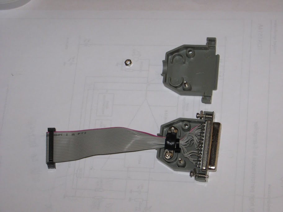
And finally a photo on your mobile electronics re:

All images can be viewed at full resolution on PICASA .


 Since the card